TrxAVR-Picastar I2C interface
See also:
I2C
PCA9555 button tasks
I2C PCA9555 board
I2C PA3AKE front end
For non-PA3AKE BPF control see TrxAVR-Picstar I2C control of a PA3AKE BPF on front end
I2C is a synchronous bidirectional communication
system that allows device to transfer data using
only two wires: a bidirectional data line (SDA)
and a clock line (SCL). Max clock rate is 400kHz.
Each device has a binary address. 7 address bits are provide
giving 128 addresses.
In most devices, three address bits are determined by hardware links to address
pins on the device (A0-A2).
The other four bits are within the device: - either software determined or hard-wired
into a
device's circuitry or firmware.
The ATmega2560 has a hardware IC2 interface.
In TrxAVR Picastar, the ATmega2560 controls
the I2C bus (master) and 'peripheral' devices are slave
devices.
The 24LC512 EEPROM is an IC2 device.
The TrxAVR colour-TFT display is controlled and programmed via I2C.
The PCA9555 chip is a
I2C to 16 I/0 line decoder which can control an alternative
BPF or any
other device you want to add that needs switching control.
The excellent PA3AKE front end and BPF units are controlled by I2C bus.
I2C connections to TrxAVR- Picastar.
I have a TrxAVR board (home brewed)
A second turned pin 8pin DIL socket is plugged into the 24LC512 socket.
The IC2 bus connection is soldered to the top if this second socket's pins.
The 24LC512 simply plugs into this second socket.
The IC2 bus needs pull up resistors.
The suggested value for these in the literature spans from
2k to 30k !! The TrxAVR-Picastar board has 4k7 pullups.
Most I2C modules have provision for pullups. You probably dont need to fit them
if the bus is only
internal to you rig and therefore
short.
At the original speed of 100kHz the I2C could operate over a few metres of cable.
We are running at 400kHz and so the maximum bus length is much shorter.
If you are chaining a lot of devices then an extra 4k7 pullup would be in order.
This would best
be located on the last item in the chain ... although this is not a matched
transmission line!!
Glenn's TrxAVR board has an I2C connector.
The new version (with the Combo Picastar board order) has a PCA9555 on board
(with logic outputs ... no on board darlington drivers)
I2C addressing
The I2C bus can in theory support 128 devices.
In practice this is limited by the design of individual I2C chips.
The address is the first byte of an I2C
read or write request.
Bit 0 is 1 for read and 0 for write. The other 7 bits are the address.
For example: the 24LC512 EEPROM
addressing is: 1 - 0 - 1- 0 - A2 - A1 - A0 - R/W
Bits 7 to 4 are fixed in the device at 1 0 1 0
Bits 3 to 1 are defined by the device's external address
select pins.
Thus because all 24LC512 devices have internal address 1010,
you can only have 8 on the I2C bus.
However, the PCA9555 chip has bits 7 to 4 internally set to
0100 .... so you can have eight of these
as well ... and so on.
My current development rig has the following I2C devices:
These involved a total of seven devices on an I2C bus. Addressing is as follows:
| 24LC512 EEPROM | 1 - 0 - 1 - 0 - A2 - A1 - A0 | A2, A1 and A0 hard-wired to 0 |
| EA TFT display | 1 - 1 - 0 - 1 - 1 - 1- 1 | Our design fixes this address |
| General purpose PCA9555 | 0 - 1 - 0 - 0 - A2 - A1 - A0 | Hobcat configures A2, A1 and A0 |
PA3AKE BPF PCA9555 |
0 - 1 - 0 - 0 - A2 - A1 - A0 | Hobcat configures A2, A1 and A0 |
PA3AKE font end roofer switch |
0 - 1 - 1 - 1 - A2 - A1 - A0 | Hobcat configures A2, A1 and A0 |
| PA3AKE front end squarer adjust AD5321 (I2c to DAC chip) |
0 - 0 - 0 - 1 - 1 - A1 - A0 | Hobcat configures A2, A1 and A0 (These have only 2 external address pins) |
| PA3AKE front end mixer bias AD5321 (I2C to DAC chip) |
0 - 0 - 0 - 1 - 1 - A1 - A0 | Hobcat configures A2, A1 and A0 (These have only 2 external address pins) |
PCA9555 interface
PCB.
The initial requirement that arose was
the need to drive BPF units with nine separate BPFs.
TrxAVR-Picastar was designed to drive a Picastar BPF unit which shares filters
between
bands and so doesn't need 9 (or more) separate lines.
IC2 is an ideal way of achieving 9 or 10 separate band select lines.
We have designed a small interface card
containing a PCA9555 and two ULN2803A
d arlington driver chips to provide relay drive from the 16 I/O lines.
This board is output only.
Note that this board is easy to design, construct
and program. It is a quick-fix to adequately
meet the needs of users wishing to drive 9+ BPFs etc. More capable and complex
IC2
interface cards may emerge later.
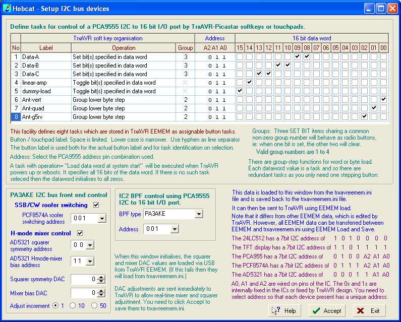
Hobcat - IC2 configuration
The screen image below
is of Hobcat's I2C configuration window.
The above window is in three separate parts:
All this
data is stored in trxavreemem.ini.
It is loaded to the screen from trxavravreemem.in (not from TrxAVR)
The Accept button saves it back to trxavreemem.ini (not to TrxAVR)
You use the EEMEM Load facility to transfer to TrxAVR.
(This loads all trxavreemem.ini data, so you need
an up to date trxavreemem.ini before you start!!)