PCA9555 button control
The PCA9555 chip is a
I2C to 16 I/0 line decoder which can control an alternative
BPF or any
other device you want to add that needs switching control.
The PCA9555 is pin compatible
with the PCF8575C but has higher output drive and more
programming options.
For and explanation of I2C and the TrxAVR I2C addressing options see TrxAVR-Picastar I2C interface
System brief description:
The IC2 configuration window
in Hobcat allows you to define up to 8 button tasks.
The tasks can be configured in a variety of ways to control the 16 output lines
of one or more
PCA9555 devices.
The tasks are stored in trxavreemem.ini from where they are transmitted to TrxAVR's
internal ATmega2560
internal EEPROM. The tasks can then be assigned to TrxAVR's touchpads and soft-keys
which then
control the PCA9555(s).
Control features include radio-button style grouping and indication of control
action status on the button label
or touchpad.
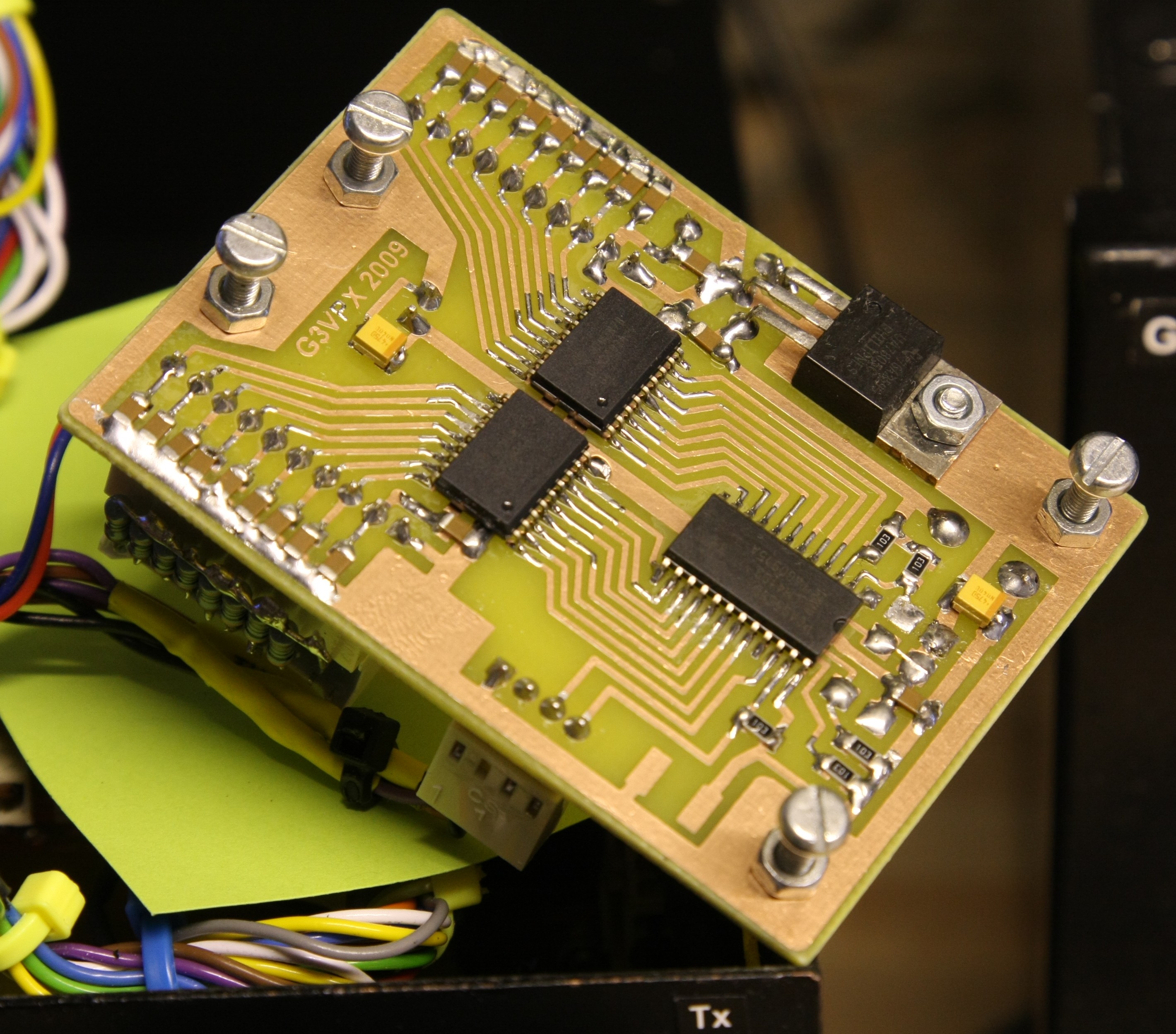
I have designed a small
board which carries a PCA9555 and two ULN2803A 8bit darlington driver chips.
See PCA9555 board
Glenn's later TrxAVR-B board (with the Combo_Picastar order) contains a PCA9555,
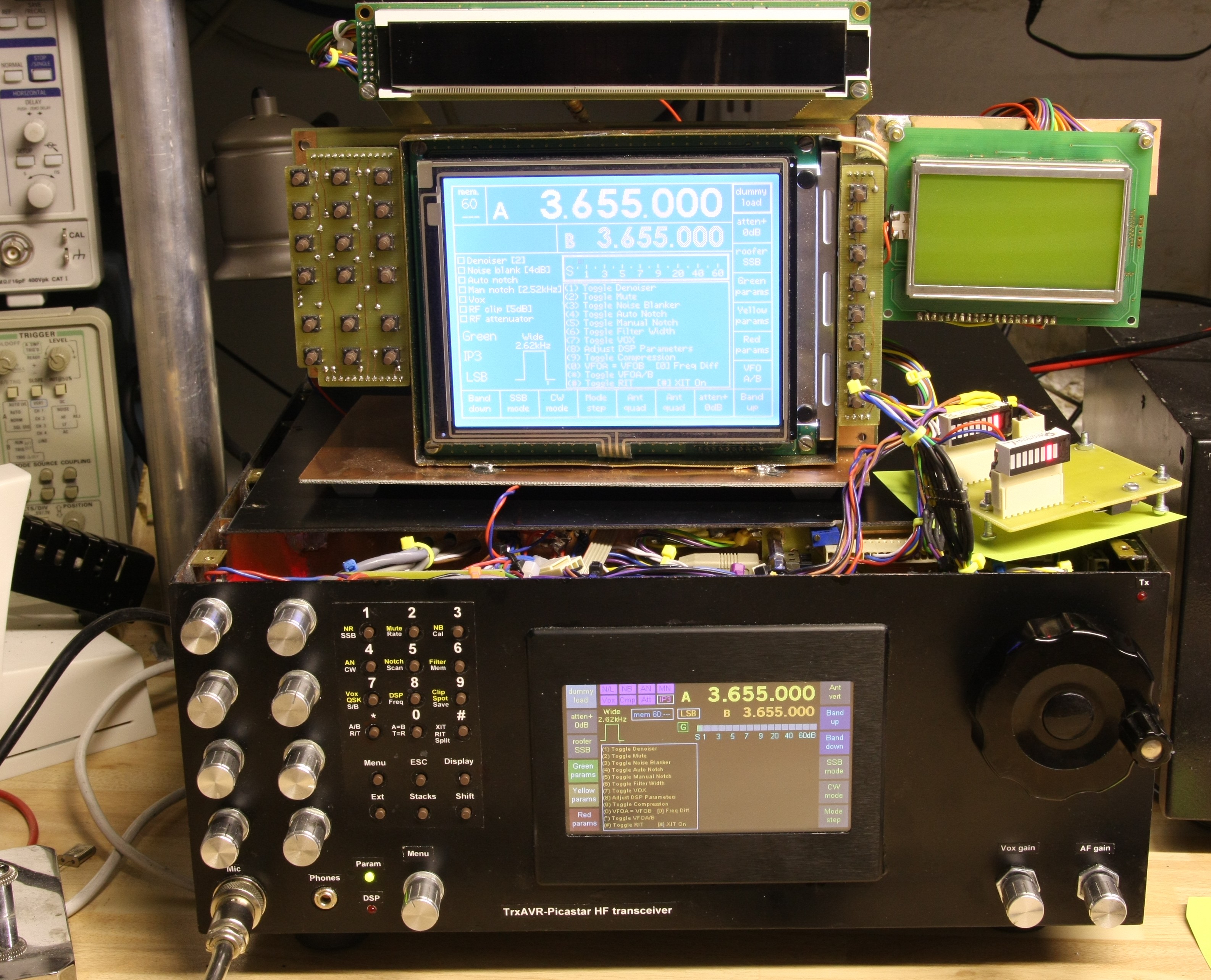
First: my test rig which use a PCA9555 board with
LEDs to display the output states:
(see PCA9555 board ) (Double
click the images below for high res)
 We
support four display types!!
We
support four display types!!
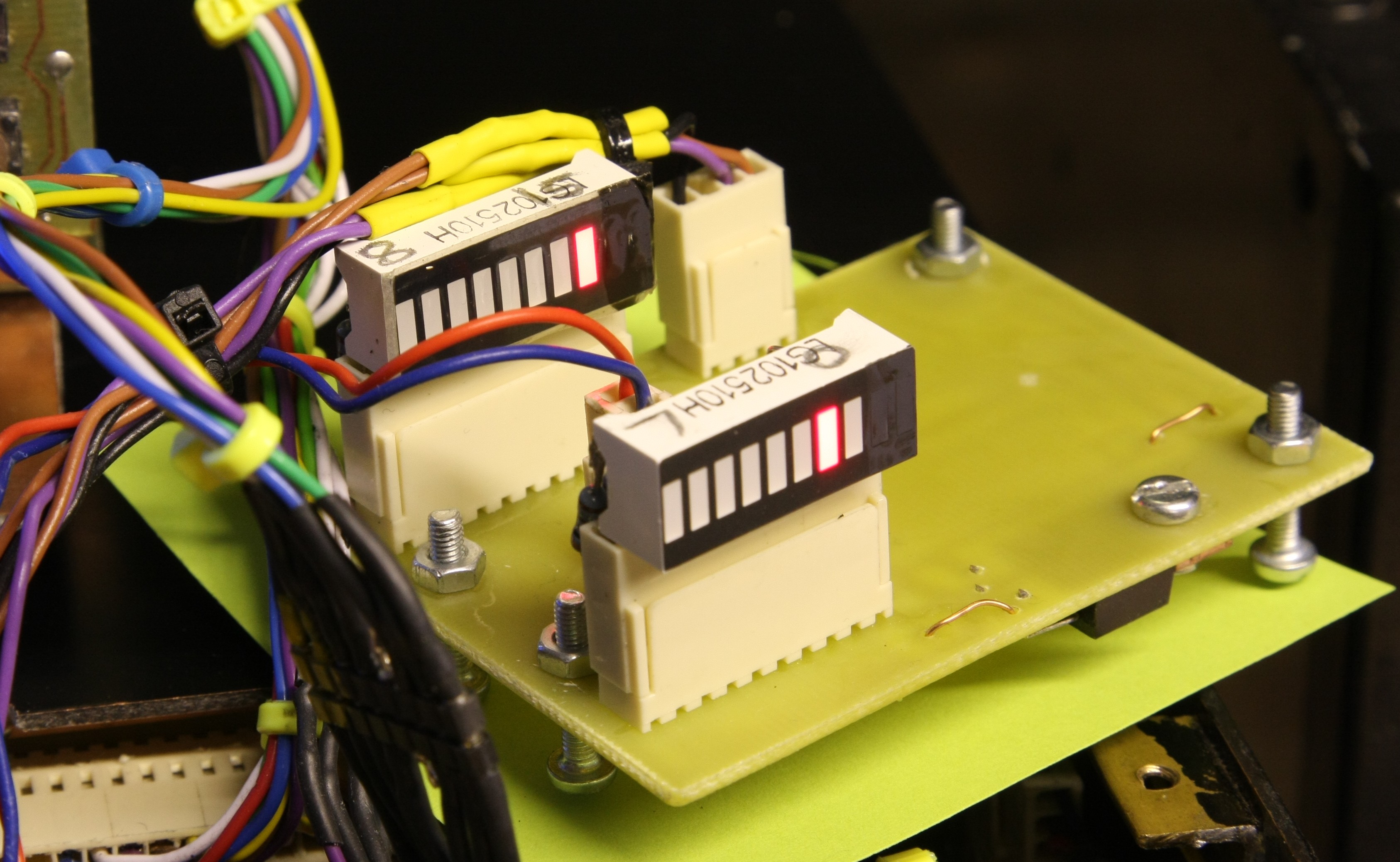
The PCA9555
board with 16 LED indicators Underside
view showing one PCA5555
(bit number penciled on top as the upper byte and
two ULN2803A darlington drivers)
is in reversed bit order!!)
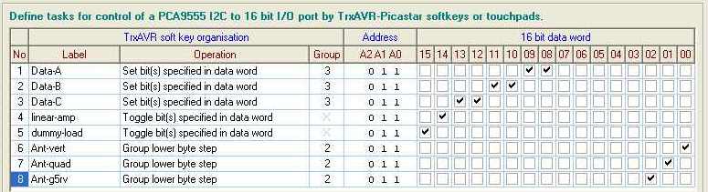
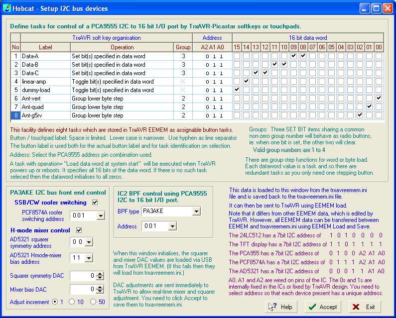
Hobcat: I2C button
task definition panel.
These Hobcat configuration settings
match the subsequent images of touchpads/button labels and their assignment
menus.
All this
data is stored in trxavreemem.ini.
It is loaded to the screen from trxavravreemem.in (not from TrxAVR)
The Accept button saves it back to trxavreemem.ini (not to TrxAVR)
You use the EEMEM Load facility to transfer to TrxAVR.
(This loads all trxavreemem.ini data, so you need
an up to date trxavreemem.ini before you start!!)
Hobcat's I2C task setup panel can define up to eight tasks which then can be assigned in TrxAVR to buttons or touchpads.
Each task has fields: Label, Operation, Group, Address and a 16 bit dataword.
Address
This specifies the device's address as defined by the wiring of its address
select pin A0, A1 and A2.
TrvAVR checks that tasks sharing a group have the same address. If not then
grouping doesn't happen!!
Dataword
This is the 16 bit dataword on which the task's actions are based.
Data entry by checking bits is much more convenient than entering decimal or
hexadecimal numbers
Label
This has two functions:
- It is an on-screen button label. The hyphen separates the
upper and lower label text.
- It identifies the task in TrxAVR's button task assignment
menus. ( Appears as: T4 linear-amp
etc)
Operation
This defines what the task does. Options are:
The ....Rx only and
...Tx only options were essential for control of preamps, linears etc
I use a PA3AKE BPF and mixer. The pre-amp between BPF and mixer must be switched
out on transmit.
My linear control button, if selected, only activates the PCA9555 output bit
on transmit.
Group
Tasks can be grouped by specifying a non-zero group number (1-4) which is common
to the tasks in the group.
Group is is only relevant to operations:
- Set bit(s) specified in data word.
- Group dataword step.
- Group upper byte step.
- Group lower byte step.
- Set
bit(s) (Tx only: clear on Rx)
- Set bit(s) (Rx only: clear on Tx)
For grouped Set bit(s)...... operations,
the buttons assigned to the tasks behave as (mutually exclusive) 'radio
buttons'.
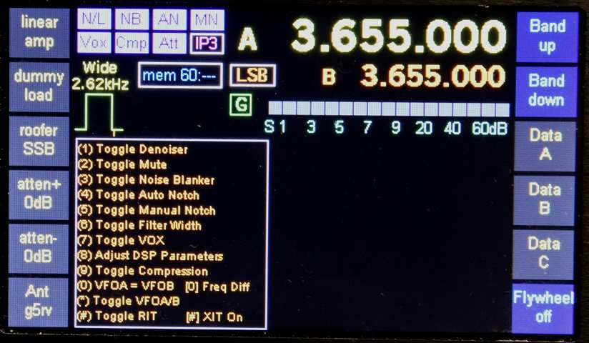
In the example below, there are three Set
bits buttons assigned to group 3. These are labeled Data-A, Data-B
and Data-C.
Data-A sets outputs 8 and 9, Data-B sets outputs 10 and 11 and Data-C sets outputs
12 and 13.
The other bits: 0 to 7 and 14 and 15 are untouched by these tasks.

When a task-button is pressed, the specified bits of the datawords of the other
tasks in the group are cleared,
and then the bits of the pressed button's task's dataword are set.
The current touchpad or on-screen button label will be highlighted. See image
below.
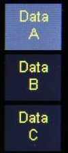 Colour
TFT Data-A selected
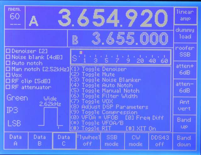
Colour
TFT Data-A selected 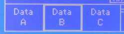 320x240 mono Data-B selected
Group dataword step, Group
upper byte step or Group lower byte step,
- the following antenna example serves to explain:

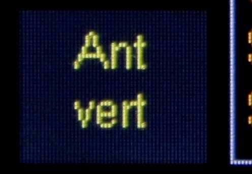
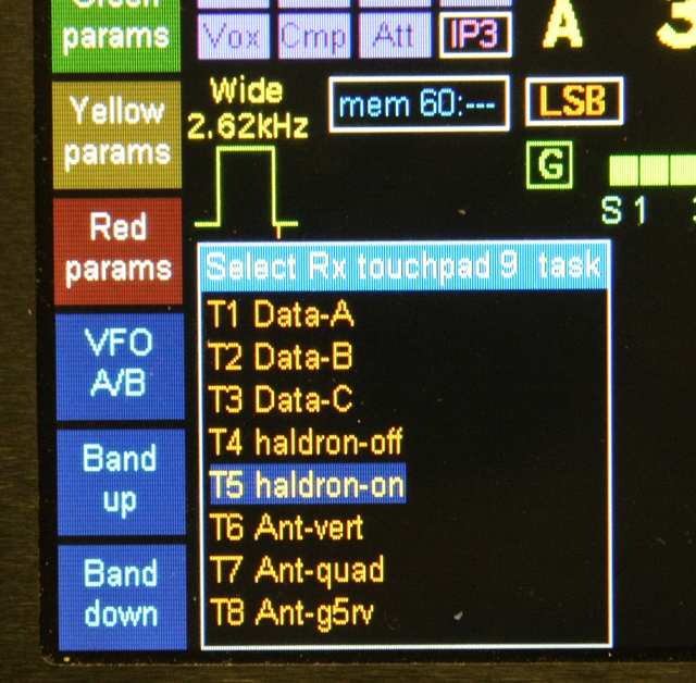
Tasks 6 ,7 and 8 are assigned to three
antenna systems. They are grouped by assigning a common group number ( 2 ).
The associated datawords are 1,2, and 4 which specify bits 0,1 and 2 respectively.
Bit 0 drives a relay to select the vertical, bit 1 the quad and bit 2 the G5RV.
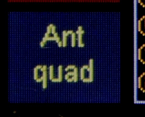
All the tasks' labels have the same top line = 'Ant' (convenient here ... but not mandatory)
ONE (and only one) of the tasks
of the group is assigned to a softkey or touch pad in TrxAVR.
At startup, the first task in the list is activated. So in this example, the
button will appear with the label Ant-vert
and the vertical will be selected.
Each press of the button will then cycle through the antennas: vert > quad
> G5RV and the button captions with change
accordingly.
If you have the same
buttons on transmit and receieve then a change made on receive with change the
transmit button
caption accordingly and vica versa.
As stated above, any one of the the button
task in the group can be selected to the single button - the caption's
bottom line will be updated automatically. If you want the same button display
on receieve and transmit,
then the hardware control will work if you use different tasks of the group
on Rx and Tx (eg: Ant-vert and Ant-quad)
BUT >>
- the caption change as you step through the task will not transfer between
Rx and Tx.
So use the the same task on Rx and Tx, eg:
Ant-qaud and Ant-quad
Note that group lower byte step controls the whole lower byte but leaves the upper bytes free for other use.
Toggle bits
Operations
- Toggle
bit(s) specified in data word.
- Toggle bit(s)
(Tx only: clear on Rx)
- Toggle bit(s) (Rx only: clear on Tx)
![]()
The examples use buttons to switch a linear
amp (bit 15) and a dummy load (bit14) in and out of operation.
The buttons will highlight when toggled to the on ( bit = 1 ) state.
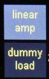 TFT
colour with linear amp on
TFT
colour with linear amp on 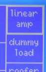 320x240 mono with linear amp on
The Toggle bits operation
works on a read - modify - write basis.
ie: it reads the PCA9555 outputs bits, changes the state of the bits specified
in dataword and writes back again.
If ANY ONE of the bits read is 0 then ALL are set to 1 so that thereafter all
specified bits change together
in the same sense.
The Toggle bit(s) Tx only and Rx
only operations operate on a copy of the data PCA9555 dataword so that
the specified bits can be cleared on Rx or TX without losing the toggled status.
The highlighting is preserved on receive and transmit.
Rx Tx paired touchpads/button labels
Many users with have the
same button task in the same place on the screen on receive and tranmsit.
The receive and transmit buttons of the pair are separate buttons.
However, if you change the state of one button of the Rx/Tx pair, then the other
will change state
to match (ie highlighting or caption).
If you Rx/TX pair Group dataword
step, Group upper byte step or Group lower
byte step, then the hardware
control will work if you use different tasks of the group on Rx and Tx (eg:
Ant-vert and Ant-quad)
BUT >>
- the caption change as you step through the task will not transfer between
Rx and Tx.
So use the the same task on Rx and Tx, eg:
Ant-qaud and Ant-quad
More I2C screen shots
Assigning
tasks to buttons -
Eight tasks: T2 etc followed by label.
Most of the visible touchpads assigned to I2C
devices. Colour TFT
The atten+ and atten- control a PA3AKE BPF attenuator. Both buttons' captions
change as the
attenuation is adjusted.
Most of the
visible touchpads assigned to I2C devices. 320x240
mono graphics.