TrxAVR-Picstar I2C control of a PA3AKE BPF on front end
Please note
that the PA3AKE I2C BPF controller used a PCF8575 I2C to 16 line device.
TrxAVR-Picastar supports the pin-compatible PCA9555 device.
It will not work with the originally specified PCF8575.
Martein Bakker, PA3AKE has developed a superb HF transceiver front end.
It consists of:
A full description of the project is at:
http://www.xs4all.nl/~martein/pa3ake/hmode/index.html
These units are expensive to build but
probably represent the ultimate in performance.
They result from a large amount of experimental work.
For example:
- Martein's H-mode mixer development evaluated 13 transformer types and 7 different
Fairchild switches.
- He found that roofing filter crystals were a significant source of IMD and
so uses high specification crystals
from EQZAL.
- The BPFs for 160m - 20m use T94 toroids.
I quickly came to the conclusion that there
was no point in building this front end unless it closely followed Martein's
design. To do otherwise would make nonsense of the huge effort that is gone
in the optimising the design.
I have built and installed the BPF unit.
My mixer/roofer board is soldered into a brass box awaiting components.
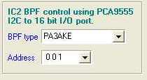
IC2 BPF control
The PA3AKE BPF unit has a motherboard into which are plugged:
The controller board uses bits 0 to 11 for filter selection and bits 12 to 15 for the RF attenuator.
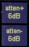
The attenuator has stages for 2dB, 4dB, 8dB and 16dB giving 0 - 30dB in 2dB steps.
Hobcat's I2C configuration window has a BPF panel:
This selects the I2C address and has the following filter select options:
TrxAVr-Picastar has a two dedicated button tasks for the PA3AKE attenuator
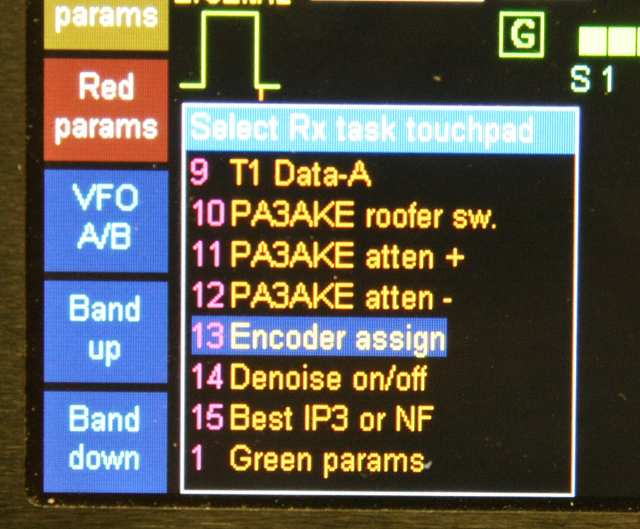
The above screenshot shows TrxAVR's Rx touchpad
assignment with these assigned to touchpads 11 and 12.
 These buttons both display the changing attenuation level (irrespective of which
is pressed)
These buttons both display the changing attenuation level (irrespective of which
is pressed)
The attenuator is automatically switched out of circuit on transmit.
For details on I2C addressing see TrxAVR-Picastar I2C interface
IC2 H-mode mixer control and SSB/CW roofing filter switching
The control devices are:
For details on I2C addressing of these devices see TrxAVR-Picastar I2C interface
Hobcat's I2C configuration window has a PA3AKE front end panel:
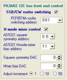
Note that the AD5321 has only two address select lines.
Roofer control
The PA3AKE roofer switch has a dedicated
button task in TrxAVR Picastar.
The above screenshot shows TrxAVR's Rx touchpad assignment with the roofer switch
assigned to touchpad 10.
 The
roofer button automatically shows the current selection (CW or SSB)
The
roofer button automatically shows the current selection (CW or SSB)
Mixer control
The AD5321s control squarer symmetry and mixer bias.
They are adjusted in real time from Hobcat
using the spin controls provided.
The levels are saved immediately to the ATmega2560's EEPROM.
However, after an adjusting session, the Accept button should be clicked to
save them
to trxavreemem.ini. (so that subsequent EEMEM loads from trxavereemem.ini will
have the
correct values)
PA3AKE
front end photos Double click for high-res view
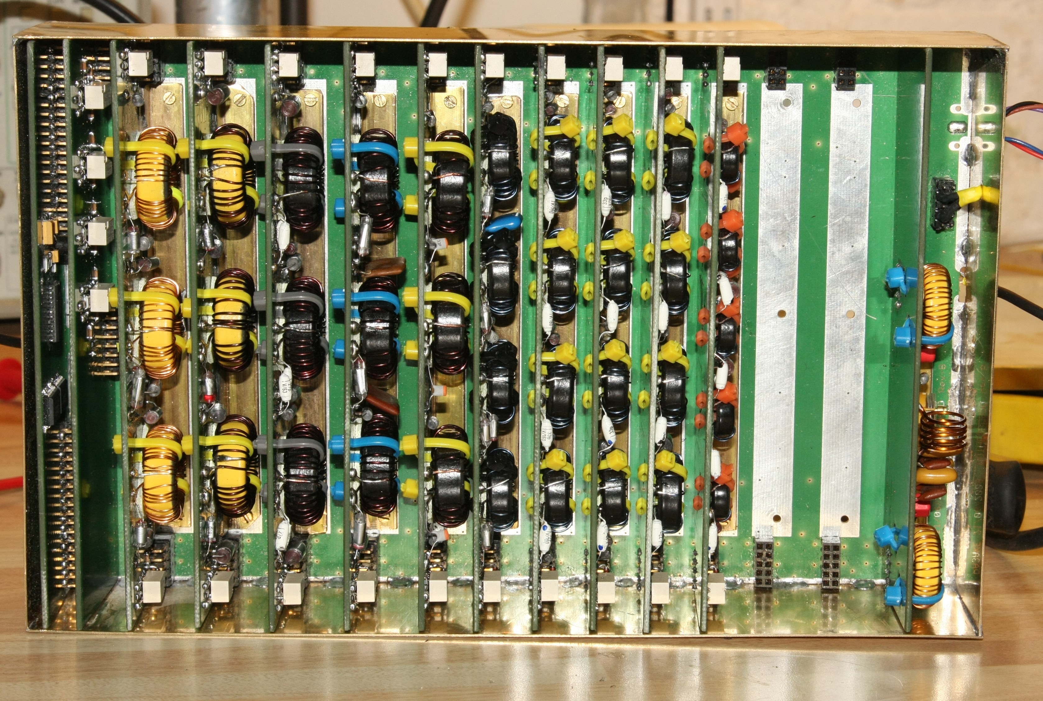
BPF top view
with 10 filters installed.
(Includes 6m but not 60m)
This uses polysterene capcitors.
(The plate ceramics shown on the 20m unit have now been replaced !!)
The flter boards provided for the alternative use of ATC ceramic caps (about
1 ukp each!)
I2C controller
and attenuator on the left. Notch filter on the right.
This uses commercially made boards from PA3AKE. For the past two years he has
had an annual
production run in October.
Unfortunately, the space in my box wasn't quite big enough. Somewhat unwillingly,
I had to trim 2mm
off each side of the motherboard and plug-in boards and 2.5mm off the top off
each plug-in board.
There is clearance to do this and the result was quite neat.
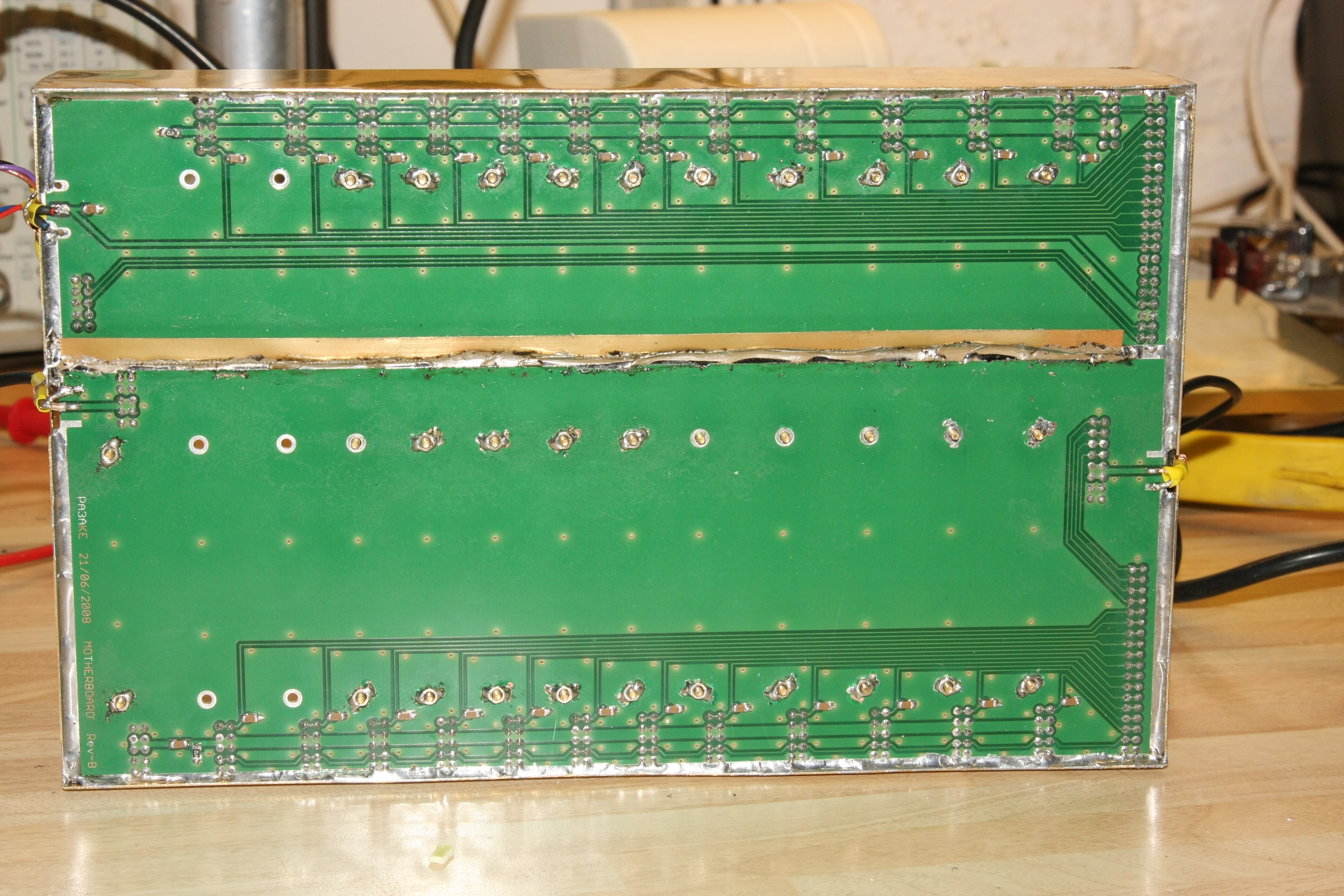
BPF underside
view.
The width reduction removed most of the tinned strip down the sides of the board.
I therefore had to scrape off some varnish to make a tinned strip to solder
to the brass box sides.
The filters are screwed down to the motherboard with M2 bolts. The 6mm M2 bolt
project downwards
to define a clearance betweenthe baord and the underlying DSPCB box panel.
Captive (soldered) brass M2 nuts have been used where possible. (not possible
directly in line
with a toroid as you cant get screwdriver access from above.)
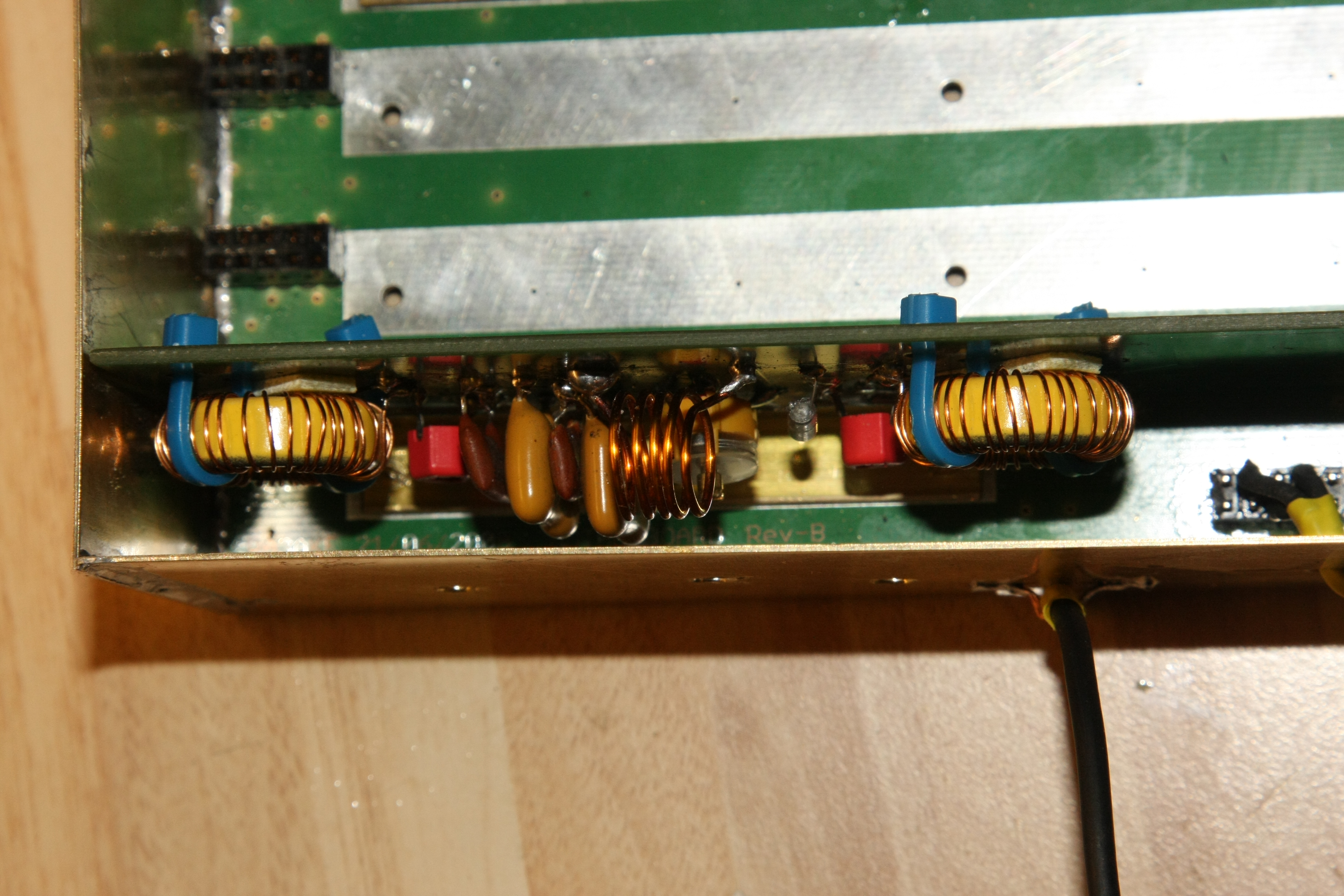
IF notch filter.
The has two shunt
and one series tuned cicuit and on my spectrum analyser
shows a notch depth of 77dB.
Top view.
I didn't use the recommended SMA connectors and power and I2C
connectors
because of space considerations.
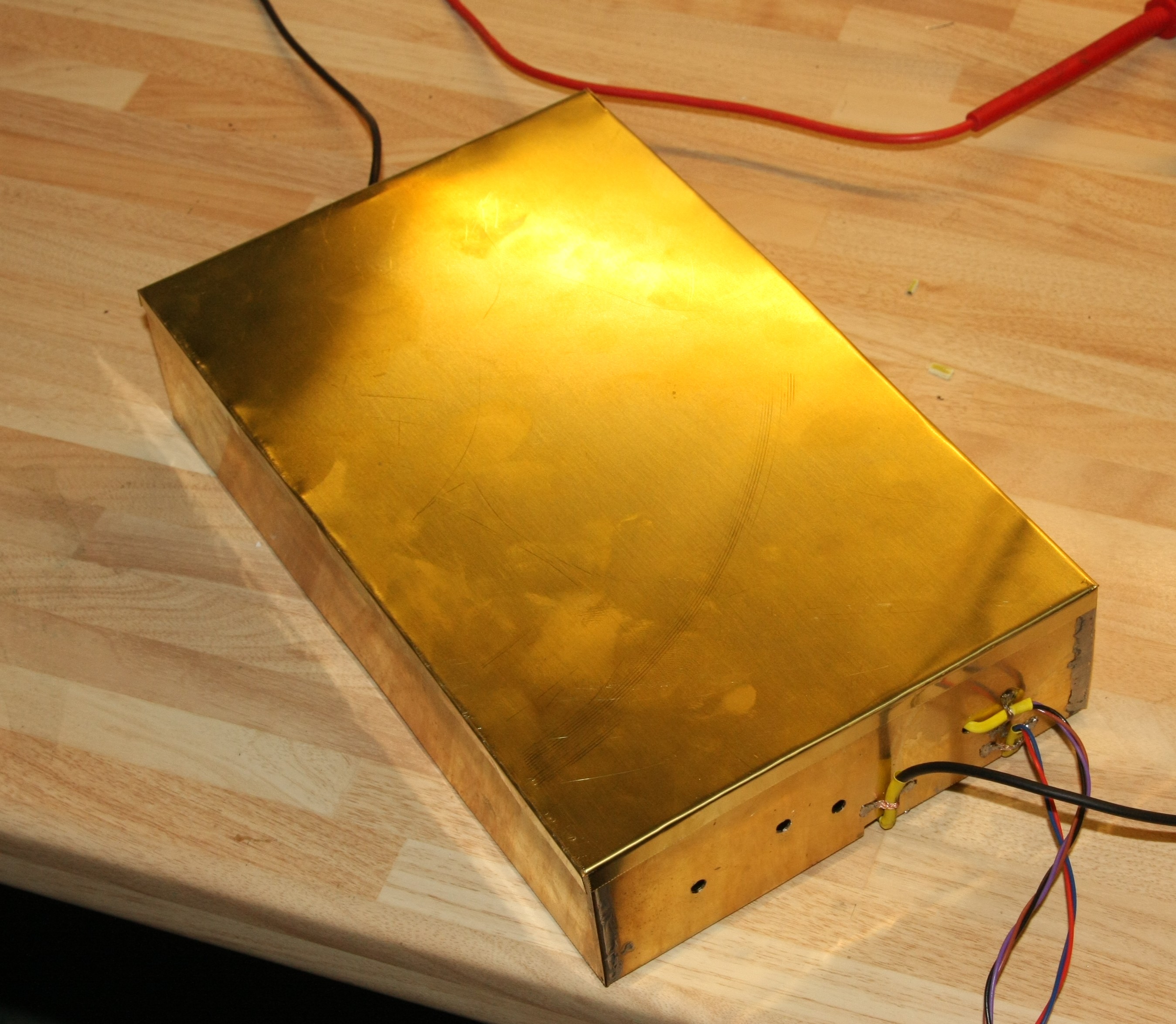
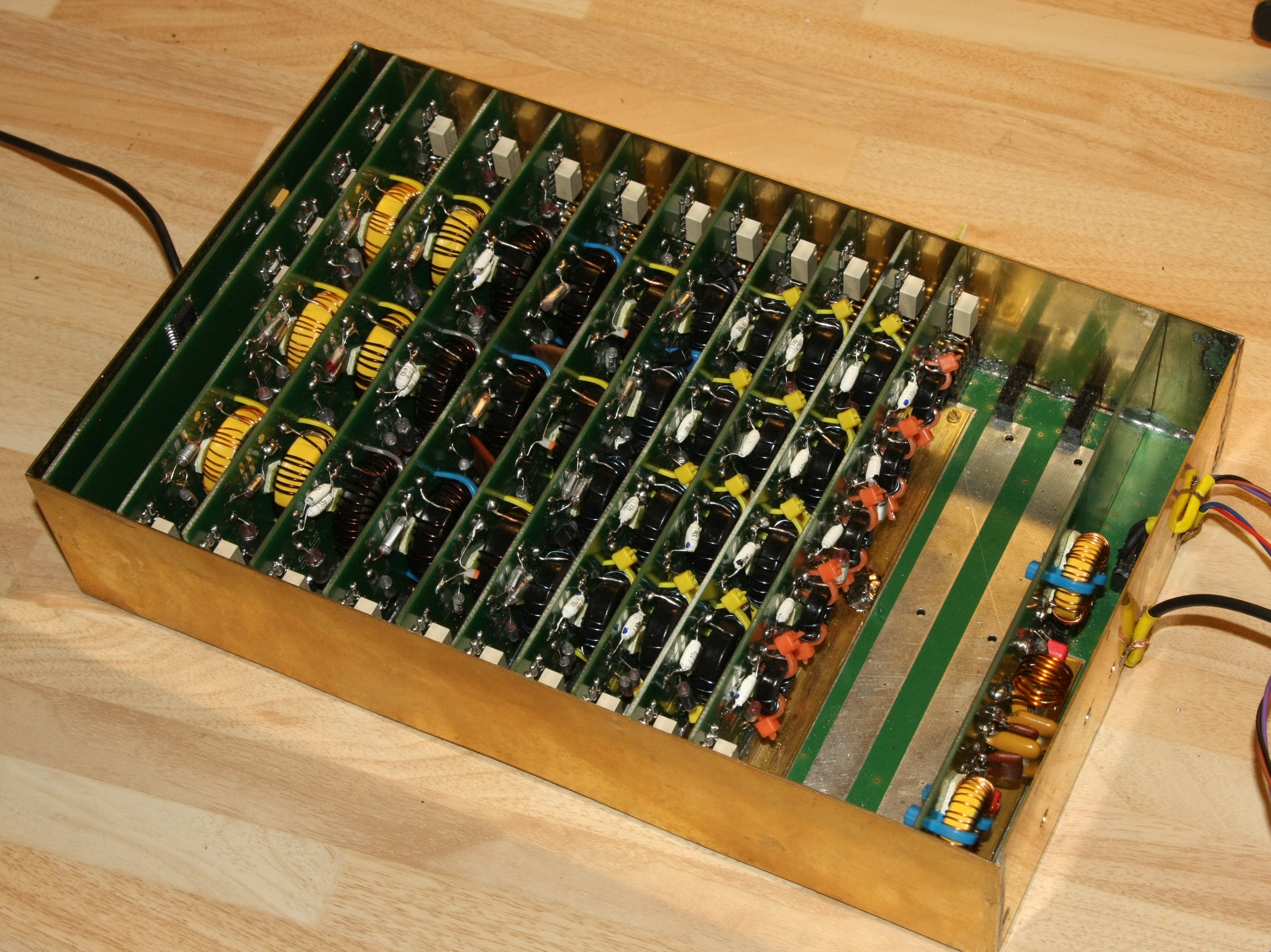
BPF box with lid
fitted. (Box is 0.7mm brass.
Lid is 0.3mm brass)
The holes are for IF notch filter adjustment.
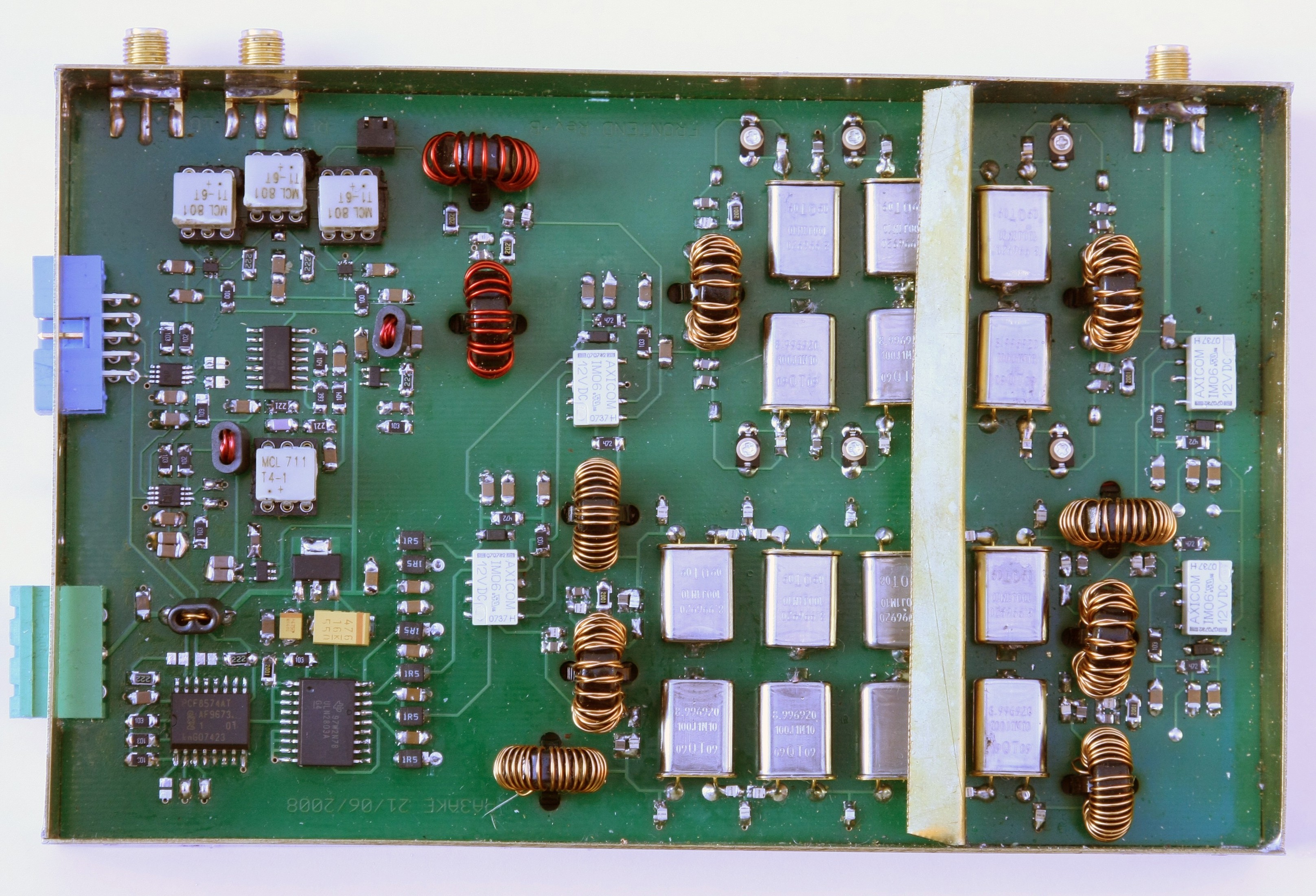
H-mode mixer
and roofing filter unit - topside
The CW filter (top
right) requires careful adjustment of the six trimmer capacitors.
The SSB filter (bottom right) required no adjustment.
The H-mode mixer is top left. The tiny FSA3157 switchs are located just below
the Minicicuits transformers.
At the left are two AD5321 I2C-DAC chips whcih provide for mixer bias adn squarer
symmetry adjustment
which is performed from Hobcat via USB.
The mid-filter screen protrudes above the edges of the box so as to spring against
the lid for good electrical
contact.
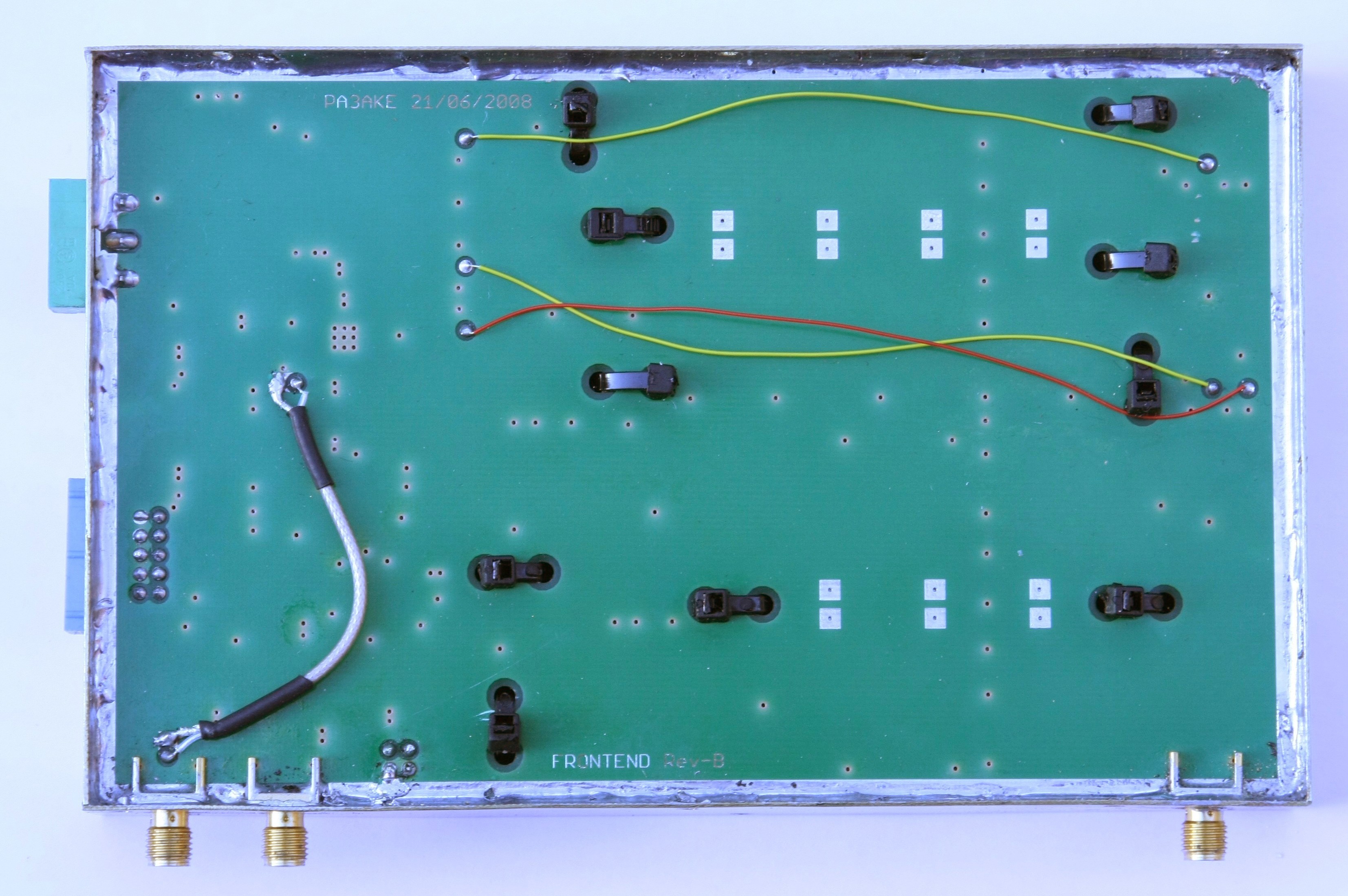
H-mode mixer
and roofing filter unit - underside
LO imput is the left most SMA connector.
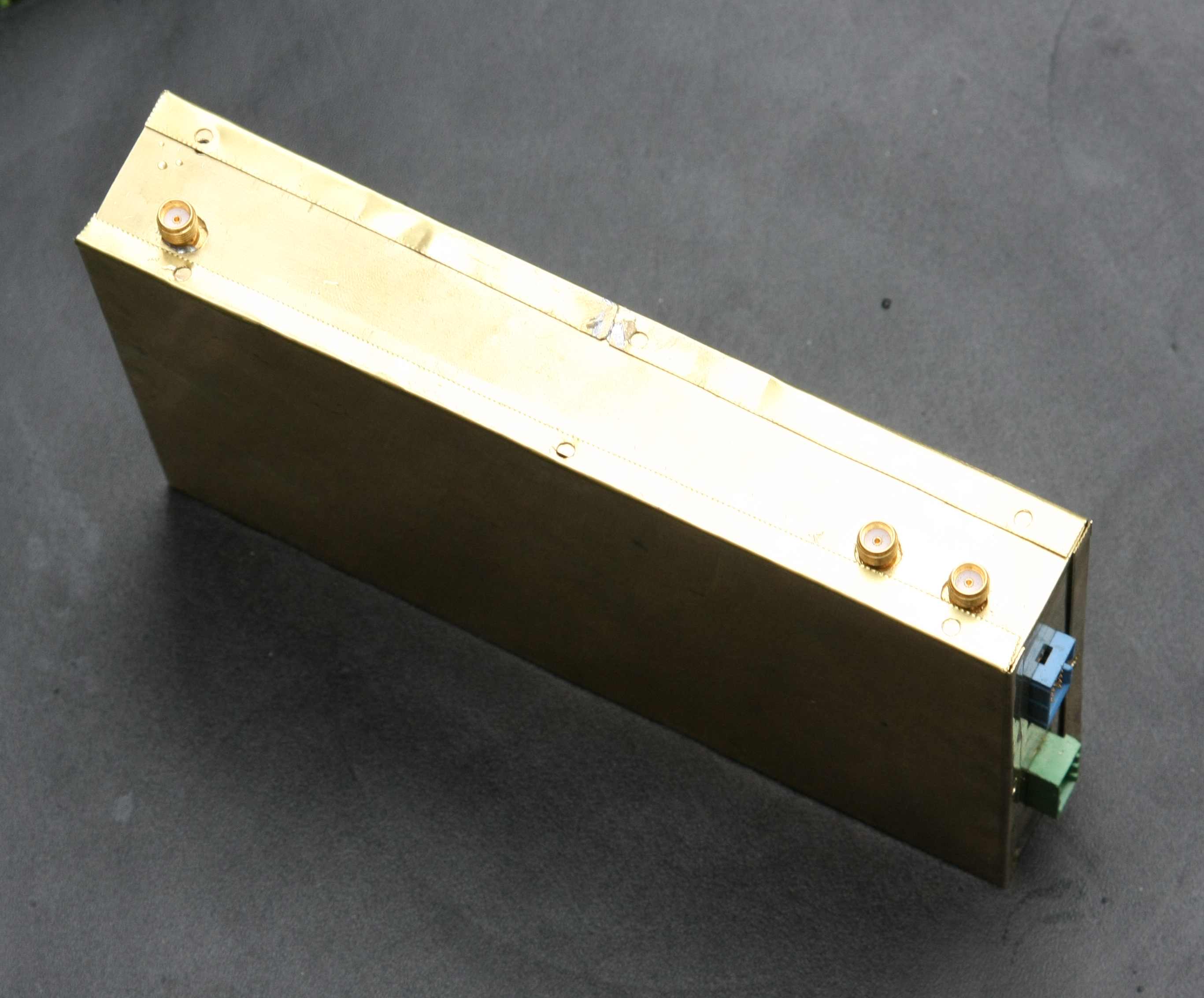
H-mode mixer
and roofing filter unit - box. Sides
0.7mm brass. Lids 0.3mm brass.