Overview
Display
It is suggested that the EA320 or equivalent display must be set to 8080 mode
(unless there is no provision other than 6800 mode).
The display type in Hardware settings must
set accordingly).
On the EA display, this involves moving the 0R 1206 link from position J68 to position J80.
Hardware faults
Please note
the hardware diagnostic software.
This should not be needed if there are no faults.
PC connections USB and COM port
Please refer to the interconnection diagram.
TrxAVR has bidirectional RS232 serial communication with the DSP unit (at 9600 baud).
TrxAVR has a single 3.5mm jack plug serial
port connection to the PC's COMn port.
If this jack is plugged in, the serial input to DSP is from the PC and not from
TrxAVR.
This allows G3XJP's QBasic setup programs such as Cal_IF13.bas to operate via
serial link.
Hobcat communicates with the PC via USB.
DSP serial and PC USB telemetry example
Please note that TrxAVR always runs with DSP parameter
5.2 set to 2.
These means that a full DSP telemetry set is continually being received from
DSP
and updating a copy in TrxAVR memory. (It is 24 byte data packet)
- The data is accessd by Smeter code and by the DSP monitor display code in TrxAVR.
- On USB request from Hobcat, it is transmitted
via USB to Hobcat for Hobcat's
DSP monitor display.
Picastar- Star folder
You need to set up a Star folder exactly as
for classic Picastar.
This is usually C:\Star2b.
If you have two Picastar transceivers, then it beter to have a separate Star
folder for each transceiver. So you could use C:\TrxAVR for TrxAVR-Picastar.
We suggest that you do this - and in fact Hobcat suggests C:\TrxAVR
by default.
Please set up your Star folder and populate it in accordance with G3XJP's Picastar
documentation.
You need to install QBasic to run G3XJP's *.bas
(See downloads
page)
(Picastar documentation and software is available on the Picaproject
Yahoo group)
DSP code and parameters being very very clear about what does what!
The DSP code is supplied in Star2b1x.xjp which is located in your Star folder.It is a text file of hexadecimal numbers. It has to be built into binary code for loading
into the DSP module. This building process incorporates DSP filter files and your AD603
callibration curve and generates checksums for error checking.
In classic Picastar this
code build is done by XJPld29.bas and is followed by transfer
via COM port direct to Picastar DSP or the 24LC512 EEPROM in PicNMix.
When loading direct to DSP, the code is always followed by setting default DSP
parameters without which the DSP unit will not operate.
When loading to PicNmix, a full set of DSP parameters is transfered to the PicNMix
24LC512 EEPROM. (ie green, yellow and red sets for CW and SSB).
The parameters are stored in USER2b2.XJP.
With TrxAVR-Picastar,
the Hobcat.exe program builds the DSP code using exactly the
same source files and algorithms. Hobcat transfers the code via USB link to
the 24LC512 EEPROM on the TrxAVR board. Hobcat also optionally transfers the parameter sets
according to menu option. (It can also save them from TrxAvr back to USer2b2.xjp.)
Hobcat can also transfer direct to DSP by COM port. This was essential in developing
the code building software.
Hobcat does not duplicate
the functions of Cal _IF13.bas, CalS_7.bas,
ParamRR0.bas,
EQ09.bas, DenTrim.bas and the loading of
test DSP code.
G3XJP's QBasic programs must be used for these functions using the the COM port
link direct to DSP where needed.
So, for example, you run Cal_IF13.bas
(under QBasic) using the serial link to TrxAVR's
DSP unit. This will save the calibration on the PC as C:\TrxAVR\Filters\AD603.DAT.
Hobcat then uses this calibration file in the generation of DSP code which is
followed by its transfer to TrxAVR's 24LC512 EEPROM.
Please be clear: you only need the serial link with TrxAVR-Picastar in initial setup.
My AD603.DAT file is dated 9 months ago. I haven't used the serial link since
then.
All the development work has used USB communication with Hobcat.
Download summary:
You need to download and install the following (all free of charge):
- All Picastar software and documentation from the Picaproject Yahoo group.
- QBasic to run G3XJP's configuration programs.
- WINAVR C code compiler for the Atmega2560 code.
- Atmel Studio 4 development environment (install after WINAVR)
- MProg from FTDI (This is the configuration program for the FT245RL USB chip)
- HobcatSetup.exe from homebrew-radios.net (This installs/updates Hobcat, and TrxAVR-Picastar and Encoders8 hex and source code,schematics, timer code etc.
Links are on Download page
You also need an AVR programmer to program the Atmega2560 processors.
The AVRISP USB programmer from Farnell costs approx. £30 and is what I have used
for development. It integrates fully with the programming code in Atmel Studio
4.
It possible to use the an alternative programmer such as PonyProg.
HobcatSetup.exe provides Hex code as well as source. In this case you might
choose not to
install WINAVR and Studio4.
Now move on to Setup 2 DSP calibration, USB
TrxAVR_Picastar setup instructions - 2- DSP calibration, USB
DSP testing and AD603 calibration
This is done using CAL_IF13.bas and XJPld2g9.bas with serial link, in accordance
with Picastar setup instructions. Working DSP code can also be loaded via serial
link.
If all is well then you hear HI on startup and the transceiver can operate with
DSP under PC control from XJPld2g9.bas.>
Configuring theFT245RL USB link.
USB devices have an EEPROM containing an identifying text strng and other configuration information.
This text pops up on the PC screen when the device is first connected.
Hobcat is programmed to look for FT245R devices but only recognises them if
'TrxAVR'
appears somewhere in the text string. (TrxAVR is not case sensitive here)
So the first task is to modify the EEPROM data. This is done with MProg.>
Switch on TrxAVR and connect by USB to
the PC - You should see a pop up box informing
you that an FT245R device has been found.
Run MProg and click Menu | Device | Scan.
You should see something like the following at the bottom.
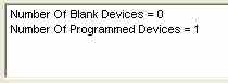
Now click Menu | Tools | Read and Parse
You will see two text boxes:
- manufacturer: FTDI
- product description: FT245R FIFO (or something similar ....
I dont have a blank one to test!!!)
Click Menu | File | Open
A file dialog window opens. Click cancel to close it - This dodge gives you access to Edit mode.
Click Menu | File | Edit The top bar will now indicate Edit Mode
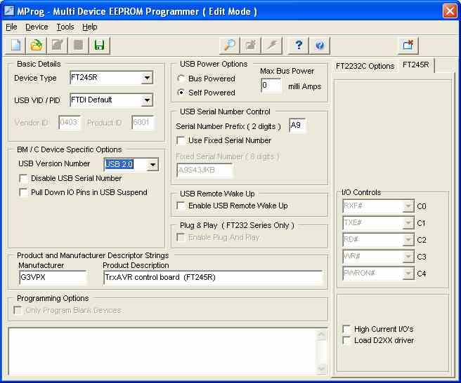
You can now edit the various visible items of configuration data.
- You must:
- Have TrxAVR somewhere in the Product specifcation string
- Set USB 2.0
- Have the device as Self Powered
My modified MProg is shown below:
To exit Edit Mode, click Menu | File | Save As
You save a copy of your edit to somewhere of your choice.
MProg returns to Program mode
Now click Menu | Device | Program The on-chip EEPROM will be updated with your edited config. data.
Terminate MProg
Switch off TrxAVB - wait 2 seconds - switch on again
Start Hobcat
Hobcat should detect TrxAVR and report this on the bottom info bar:

This is not dependent on operation the ATmemga2560 processor (which may not yet have been programmed)
Note the COM1 message.
This means that Hobcat's COM port selection is COM1 and that is is available.
The only use of COM1 is direct load to DSP. You may never use this.
The next step is to program the TrxAVR
ATmega2560 and the Encoders8 ATmega2560.
(With TrxAVR-B, both processors are on the same board and so there are two six
pin programming sockets)
Now move on to Setup 3 Atmega2560 programming
TrxAVR_Picastar setup instructions - 3 - Atmega2560 programming
Preparing for Programming the ATmega2560
These instructions refer to programming from Studio 4 using an AVRISP USB programmer.
Other programmers can be used, either using the downloaded hex code or generating
it from source code with WINAVR/Studio4. See Ponyprog
Install WINAVR and then Atmel Studio 4.
Create a folder somewhere on your PC (in your Star folder if you wish) and name it trxavr_source.
Unzip C:\Program files\hbradios\hobcat\trxavrcode\trxavr_source_NNN.zip into the trxavr_source folder.
If you are using Encoders8, then create another folder named encoders8_source.
Unzip C:\Program files\hbradios\hobcat\encoders8code\encoders8_sourceNNN.zip into this folder.
Start Atmel Studio 4.
Click Menu | File | Open file
Locate your trxavr_source folder and find TrxAVR.aps.
Click Open
The project will load with all the files in cascaded pages. - You can maximise
one to tidy the screen.
Click Menu | Buiild | Rebuild all You should eventually see a message bottom left of the form.
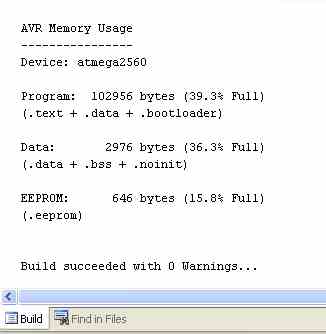
If it says build succeeded with 0 warnings then all is well.
Run windows explorer and look in your trxavr_source folder. You will a new subfolder named default.
In default you will find TrxAVR.hex and TrxAVR.eep.
If you are using a different programmer (eg: PonyProg) then
you will use this TrxAVR.hex file for programming.
(TrxAVR.eep is internal EEPROM data defined by the source code.
It is not important to load it because you will later use Hobcat to load the internal EEPROM from trxavreemem.ini)
Programming
Connect the AVRISP programmer to TrxAVR using a 6way IDC cable and by USB to the PC.
In Studio4, click Menu | Tools | Program AVR | Auto connect
The programmer appears:
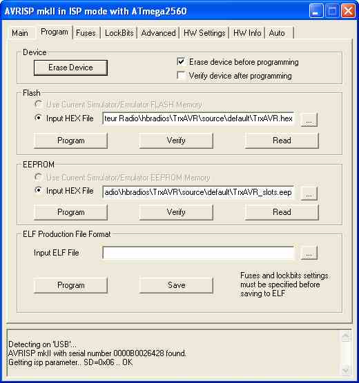
Make sure that the Erase before programming box is checked.
You dont want this to erase the internal EEPROM, so in the Fuses tab set EESAVE as shown below.
The hex file automatically defaults to the one you have built (but can be changed).
Click Program in the Flash section to load the code.
Then, as this is the first time, click Verify to check that all is well.
There is no need to program the EEPROM. Hobcat will do it.
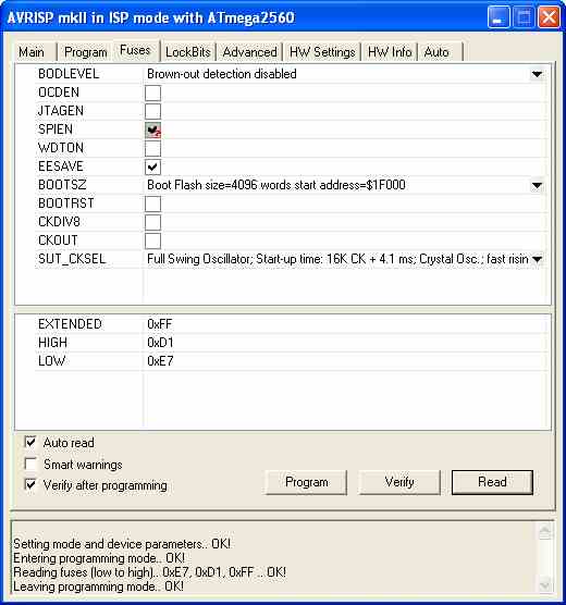
Click the Fuses tab.
This should be configured as shown below.
(You must set the SUT_CKSEL as shown, otherwise the clock oscillator
will not run.)
The Fuses tab has Auto read set and so reads the settings from the ATmega2560 as soon as you open the tab.
Configure as shown below and then click Program.
******* Warning: Do not set SUT_CKSEL to an external option.********
In-situ programming needs the clock to be running. The ATmega2560 is supplied with
the internal R/C clock oscillator selected - so you can program it. Switching
to internal oscillator using the 16Mhz crystal allows you to program it. BUT - if
you select a non-existent external clock source, then you thereafter have no clock and so
you are effectively locked out. ie: you cant program the chip and so so can't change
back to a working clock option. To recover from this sitiuation you need to apply an external
clock signal (eg: from the other ATmega2560 using a piece of wire and a capacitor!)
(The ATmega2560 can be programmed in 'High Voltage
Programming Mode' wihout a clock running. However, we cannot do this. It needs a special programmer with a parallel
data interface to the chip.)
After programming or setting fuse, the ATmega2560 will automatically reboot.
If your display is graphics, then the display will not operate. This is because the default display is the 20x4 character display. You wont see anything until you set the correct display type using Hobcat.
TrxAVR-Picastar normally starts with a
Loading DSP code message and a progress bar.
DSP code loading takes about 20 seconds.
If the 24LC512 EEPROM is blank then this loading phase will be bypassed and
the
TrxAVR display will go direct to the working 'home ' state.
The frequency display will be zero because no sticky slots are loaded, and these
include the power on slot.
Classic Picastar has default values for the 61 sticky F+M slots coded in source code.
TrxAVR doesn't. They have to be loaded by Hobcat from trxavreemem.ini
to Atmega2560 internal EEPROM.
This facility to load and save from an INI file allows you to edit the slot
data on the PC.
Programming Encoders8
If you are using Encoders8 (built into TrxAVR-B) then you need to program the ATmega2560 in Encoders8.
In Studio4, click Menu | Project | Close project and
thenMenu | File | Open file
Navigate to your encoders8_source folder and open encoders8.aps.
Then build as for trxavrcode above. A subfolder encoders8_source\default
will contain encoders8.hex
Connect your programmer to the Encoders8 board programming socket (or to the Encoders8 programming socket on TrxAVR-B) and program the Encoders8 Atmega2560 as described above for the TrxAVR ATmega2560.
Testing the processor and USB
You should now be able to run and test the TrxAVR-Picstar code an USB link opration.
Restart TrxAVR-Picastar
Ensure the USB connection from TrxAVR to PC is in place. (I dont mean the programming
connection)
(Please note that if the AVRISP USB programmer is connected to TrxAVR, then it must be powered by being connected to the PC. Otherwise the ATmega2560 will not run)
Run Hobcat
It will show detection of TrxAVR on the status bar.
You need to check that TrxAVR-Picastar code is running so that USB communication
is possible.
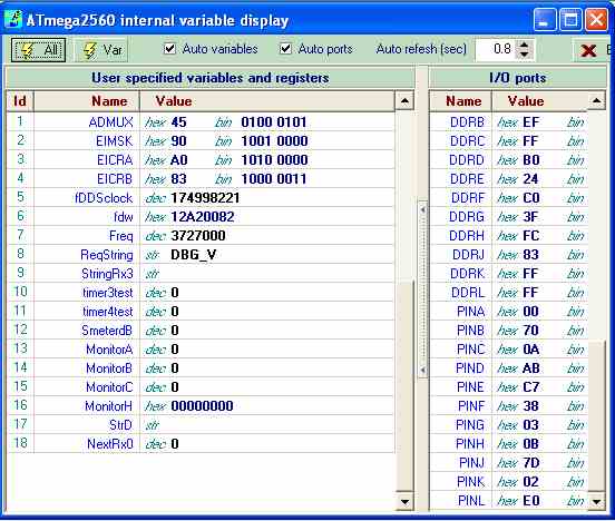
To do this, click the Debug button in Hocat. The Debug window
will appear and should report the
state of the Atmeg2560's ports and twenty or so variables. The variables are
specified in the TrxAVR code
and so if your can see them, then they have arrived by USB link!
The debug Window is shown below:
Close the debug window
Timer code - programming the timer PIC
HobcatSetup.exe installs modified code for Picastar's Timer board PIC processor.
The files are stvox04_padis.asm and stvox04_padis.hex.
They are loaded into C:\Program files\hbradios\hobcat\timercode
The modified code uses the hitherto unused RA4 pin to disable PA bias.
If RA4 is low on receive, the bias remains
disabled on switch to transmit.
If RA4 goes low on transmit, the bias is disabled. If RA4 then does high again,
the bias will not enable until a switch receive and then back to transmit.
Now move on to Setup 4
TrxAVR_Picastar setup instructions - Configuring via USB
Hardware Setup
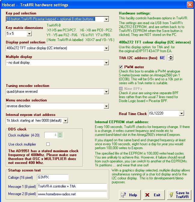
Click Menu | Setup | Hardware config The hardware
configuration window appears.
It is shown below configured for EA320 graphics + touch panel + 25 key pad.
You need to configure it for your hardware by selecting from the drop down lists.
Please note that
the EA320 or equivalent display must be set to 8080 mode.
On the EA display, this involves moving the 0R 1206 link from position J68 to
position J80.
There was an earlier problem caused by selecting a colour TFT display in Hardware
Settings, when no TFT display was connected. Recurrent I2C wait states delayed DSP load to
over 2 minutes and USB communication was thereafter unreliable. (and you need USB to change
hardware settings!!)
This problem no longer exists: If the first write to the Tft display fails,
further comunication is abandoned and DSP load and subsequent operation are normal (albeit with a screen display)
Finally click Save to TrxAVR.
Then restart TrxAVR ... your display and key pad should be active.
As stated above, the display may shown zero frequency because no Power-on slot
data is yet loaded.
Setting your Star folder
In Hobcat, click Menu | Setup | Star Folder.
Your will see the window below with C:\TrxAVR selected by default.
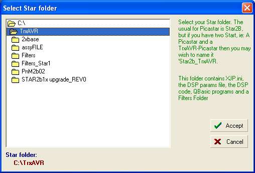
Accept C:\TrxAVR ... or change your Star folder to something different.
DSP parameter file
The default parameter file is USER2b2.XJP. The location of this file is specified in XJP.INI which is located in your Star folder.
Hobcat provides an editor
to change this filename entry in XJP.INI. The file must be preexisting.
Click Menu | Setup | Select DSP parameter file. The following window appears:
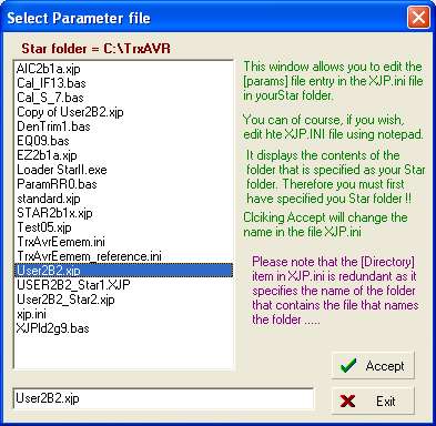
The file window shows all the files in your Star folder and defaults to User2b2.XJP.
DSP code and params to TrxAVR
Click Menu | Tools | DSP EEPROM loaders USB | Code and params to TrxAVR
The window shown below appears. Click Proceed
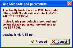
Code and params should transfer in under 3 seconds.
Then you should have the window below showing matching checksum values
and Params sent ok
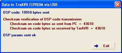
Click Exit.
Click Menu | Tools | DSP EEPROM loaders USB | AD603 calibration to TrxAVR
The following window appears:
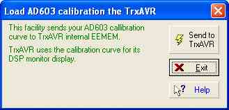
Click Send to TrxAVR.
Note that the AD603 calibration is sent to TrxAVR for use in the DSP monitor gain displays.
It has no other use in TrxAVR and so is not used with a character or 128x64
graphics display.
EEMEM data to TrxAVR
- The ATmega2560's internal EEPROM contains:
- DDS clock frequency value
- LSB and USB offsets
- DSP parameters assigned to eight encoders and two pots.
- Fifteen Rx soft key function assignments
- Fifteen Tx soft key function assignments
- Touch panel calibration
- Memory, VFO and Band sticky slot data
- Display bright and dim levels and auto-dim seconds
- DDS44 CW mode (ie CWU or CWL)
- Software flywheel on/off
- Autodim on/off
- Parameter reset mode (DDS39)
This data is transferable to and from C:\TrxAVR\trxavreemem.ini
A default version of the file trxavreemem.ini was installed by HobcatSetup.exe.
Copy trxavreemem.ini from C:\Program files\hbradios\hobcat\trxavrcode to C:\TrxAVR.
Examine it if you wish by opening the file in Notepad. It contains default data based on Picastar's defaults.
You may wish to change some slot data.
In Hobcat, click Menu | Setup | Load/Save EEMEM. The following window appears
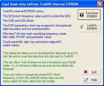
Click Load to EEMEM.
The following confirmation appears.
(The load is not error checked)
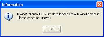
Restart TrxAVR-Picastar, You should see the default power-on frequency, 3727000 on both VFOs.
DDS clock and offsets
There are three ways to set DDS clock and LSB and USB offsets.
Using DDS 33, 31 and 37.
You can set DDS clock frequency and
LSB and USB offsets as directed in the
Picastar setup instructions, ie: using DDS[9]33, DDS[9]31, and DDS[9]37.
From Hobcat
Click Menu | Setup| DDS Clock, Offsets. The window below appears: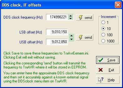
You can adjust clock and offsets, The offsets
move together and remain 2.7kHz apart.
Click send to send to TrxAVR-Picastar. Click Save to save in trxavreemem.ini.
- Offset setting operates as DDS31 and DD37 in signal generator
mode.
- DDS clock setting does not switch to signal generator
mode
This allows you to calibrate to a received signal of accurate known frequency.
SWR meter calibration
TrxAVR-Picastar, on transmit,
has a power meter which displays forward and reflected power and SWR.
Hobcat has a calibration facility for this power meter. This works via USB link.
Calibration profiles are stored in the PC and loaded via USB the TrxAVR-Picastar.
The final setup step is to perform this calibration.
Please return to the menu and access the SWR meter pages