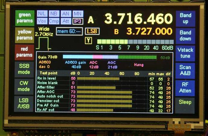
The above image is of an SSB receive display with the DSP monitor added keyimg the Display switch.
Colour TFT screenshots
These images are on a 4.3 inch
eDIPTFT43-ATP 480 x272 intelligent TFT colour display
from Electronic Assembly.
Most builders are using a 4.3 or
5inch display panel with the TftA driver board.
The display content is the same.
These images pre-date the addition
of Real Time Clock support. See: Real
Time Clock
The above image is of an SSB receive display with
the DSP monitor added keyimg the Display switch.
At each side are six touch buttons
which each be menu-assigned to one of fifty DDS, DSP and other tasks.
Each task carries button colour data: green, yellow and red for parameter set
switching, blue for other
DDS functions and dark grey for DSP functions.
Separate assignments are made for transmit and receive (but can be the same).
The top part of the screen shows basic
operational information, ie: A and B VFOs, switches, S meter etc
The lower part is available for other displays - only DSP monitor is available
at present and is is shown above.
The surrounding stripes are the electrodes for the resistive touch screen.
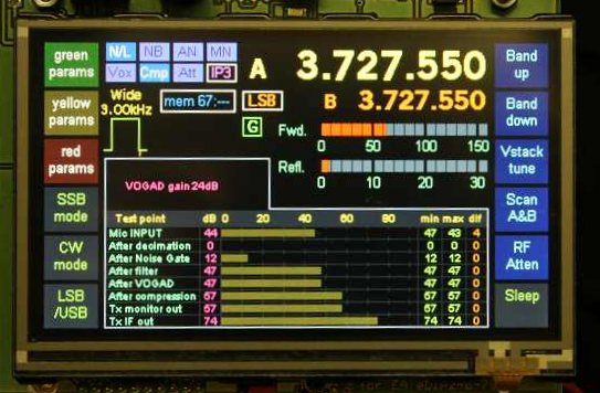
On switching to transmit, the S meter is replaced by the SWR
meter and the DSP
monitor (if displayed), changes to the transmit version. With DSP monitor showing,
SWR is not displayed (ie: forward and reflected power)
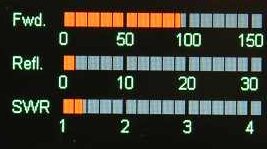
With no DSP monitor, there is space for Forward power, Reflected
power and SWR indication.
Power ranges and calibration are set by Hobcat's Forward and Reflected SWR calibration
facility
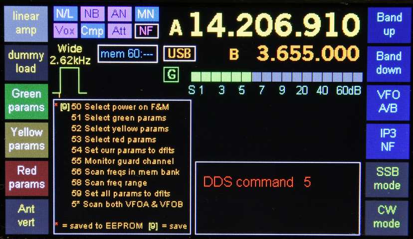
DDS commands on the 4x3 keypad
operate exactly as Picastar, but with on screen indication as above.
(The message above results from a long key press on the 5key and awaits the
next key press)
The help window o nthe left shows all the DDS5n commands
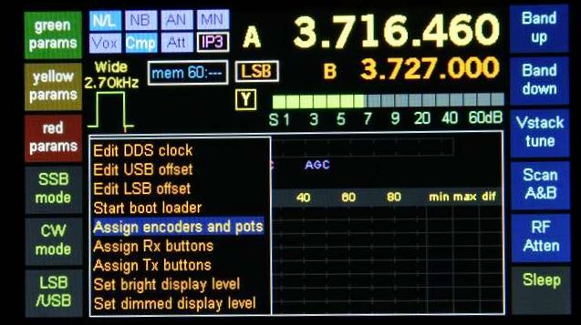
Main menu
superimposed over DSP monitor (from pressing the Menu
key)
(Rotate menu-encoder to highlight required item and then key
Menu to select)
The DSP monitor halts but remains on-screen.
On exiting from the menu, the DSP monitor is redrawn and restarts.
(Note that the boot loader option was experimental and is no longer provided)
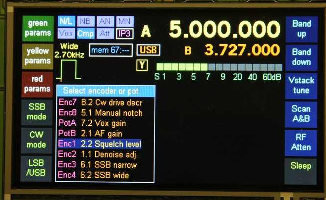
Encoders and Pots assign sub-menu - this
show the current assignments.
(Rotate menu-encoder to highlight required item and then key
Menu to select)
 t
t
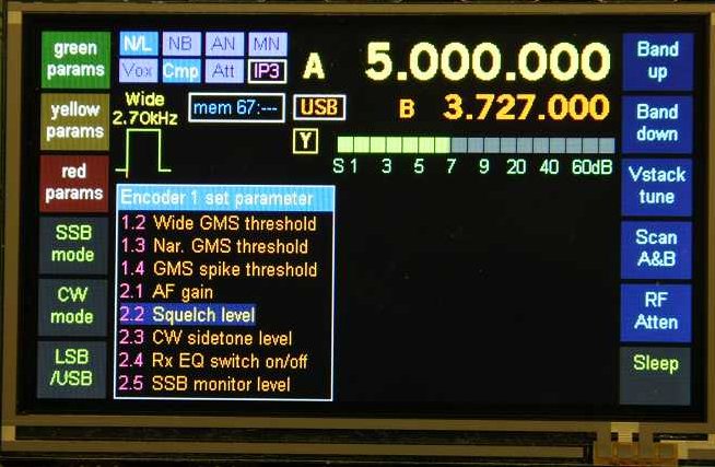
Setting the DSP parameter assigned to Encoder
1
(Rotate menu-encoder to highlight required item and then key
Menu to select)
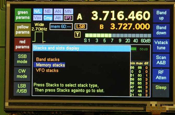
Stacks menu. This is accessed
by the Stacks key.
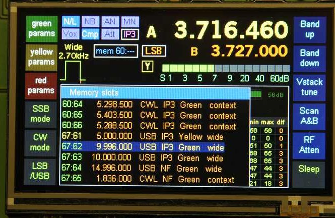
Memory stacks and slots sub-menu. The
stacks and slots are labeled in accordance with DDS key pad
selection codes, ie: 60:64 is stack 60 slot 64.
Rotate menu encoder to highlight and then key Stacks
to select the slot.
This loads the slot but does not enter stack tuning mode (see Picastar manual
for this)
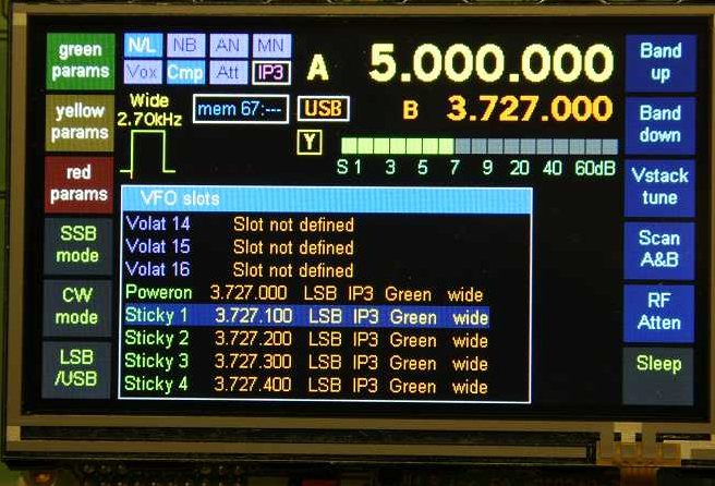
VFO slots sub menu. - TrxAVR VFO
sticky and volatile slots behave as described
in the Picastar manual.
The display is for viewing only. You cannot load a VFO slot form this menu.
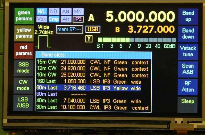
Band slots sub-menu. SSB,
CW and Last slots for each band (except 60m)
Rotate menu encoder to highlight and then key Stacks
to select the slot.
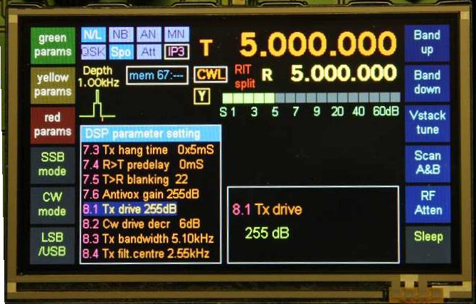
Adjusting parameters.
The highlighted parameter is selection using the menu encoder
OR via the keypad as in the Picastar manual.
The value is adjusted using the tuning encoder.
When adjusting filter width or depth the filter graphic responds as the adjustment
is made.
If you have SSB-wide selected and adjust SSB narrow,
then DSP operation and the filter graphic
temporarily switch to narrow. They revert to wide
again after the adjustment.
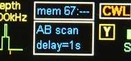
VFO A /B alternating scanning indication.
(Tuning encoder sets scan interval as described in Picastar
manual)
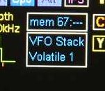
VFO stack tuning indication (DDS27).
See Picastar manual for behavior of volatile and sticky slots.
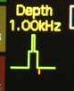
The filter
graphic is show above for CW mode with the
filter Context/Depth switch set to Depth.
The small red mark is the carrier frequency marker.
Please note
the behavior of carrier frequency offset setting
(which has been programmed to behave exactly as in the Picastar manual)
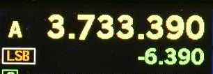
Frequency difference display -
Hold the 0 key or hold the # key (XIT mode)
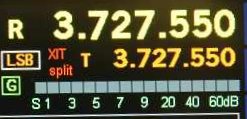
XIT and split indication
XIT mode is entered by a long
press on the # key. VFOs are labeledR
and T and XIT split
is sown in red.
A short press on the # key then toggles split on/off
whilst maintaining XIT mode.
Holding the # key show frequency difference. (In classic Picastar
you only see the frequency difference
display whilst holding # AND tuning. Such
a restriction is unnecessary in TrxAVR-Picastar becuase both
VFOs are visible.